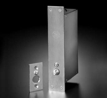
401 Electric Deadbolt
Rixson
Application
• For use with swinging, sliding, power operated and vertical lift doors.
• Model 401 (Fail Safe) – Locked when energized – unlocks automatically in case of power failure. Under normal operation, deadbolt extends when door is closed and control switch is in "lock" position.
• Model 401R (Fail Secure) – Unlocked when energized – locks automatically in case of power failure. Under normal operation, deadbolt extends when door is closed and control switch is in "lock" position.
Operating Voltages
• Voltage: 24VDC, 6.25 amps inrush, 0.42 amps seated.
• Solenoid Voltage: 120VAC or VDC (optional).
Note: Junction box is supplied with 120V deadbolts (to comply with UL requirements).
• Indication Switches: Single pole, double throw type (SPDT). Ratings: 10 amps @ 125 or 250VAC. (Optional only.)
Note: All deadbolts are actuated by DC solenoids. When primary power source is AC, the deadbolt is supplied with an internal bridge rectifier.
Product Description and Features
• Indication Switches – Internal switch(es) to monitor the position of the deadbolt. This feature can be used for remote door monitoring, to control alarms, indicating lights, interlocks and automatic door operators. One or two switches can be supplied, depending on circuit requirements.
Specify switch options by letters:
BL – a switch that indicates when the deadbolt is fully extended.
BUL – a switch that indicates when the deadbolt is fully retracted.
Note: When door is open, the door-position switch tripper can be manually depressed, thereby giving a false indication that the door is locked. This can be eliminated, if desired, by installing a door-position indication switch and wiring it in series with the indication switch(es) in the deadbolt. Then, a “secure” signal can be produced only after three conditions have been met: 1) door-position switch tripper is depressed 2) deadbolt is extended and deadlocked, and 3) door is closed BL/BUL.
• Manual Release – The deadbolt may be modified for overriding the electric operation, allowing for manual unlocking from one side only. Specify “MR”. This feature may be adapted by the customer for a customized unlocking system, or
by the following, factory-supplied accessory items, which must be purchased separately (see page 251 for options):
Detention or commercial rim key cylinders (by others).
Key Cylinder Holders – Holds and protects the key cylinder used for manual unlocking. They are available in three styles, depending on where the holder is located:
• Hinge – For the hinge side of a door frame, when the 401 Electric Deadbolt is mortised into either the door header or jamb.
• Stop – For the stop side of a door frame, when the 401 Electric Deadbolt is mortised into either the door header or jamb.
• Rim – For mounting to the surface of either a rim housing (401-RM) or fence-gate housing (401-118).
Finishes
606, 612, 613, 625, 626
401RM Rim Housing
Application
For use when rim-mounting the 401 Electric Deadbolt.
401-RM
RIM HOUSING – A two-piece housing which encases a 401 Deadbolt for mounting on the surface of a door frame. The housing and cover are made of 10-gauge, cold-rolled steel and have a primed finish. The 401 Deadbolt must be purchased separately.
401-RM-MR
Allows mounting of manual release cylinder holders.
401-125
DOUBLE-SIZE RIM HOUSING – To accommodate two 401 Deadbolts for mounting over pairs of doors.
401-90
ADJUSTABLE RIM KEEPER – Must be purchased separately. It is adjustable from 1" to 2", from centerline of bolt to face of door. If more than 2" is required, a 2" to 3" adjustable rim keeper is available.
Standard Finish
Standard finish, 600, prime
Optional finishes
606 Satin brass
612 Satin bronze, clear coated
613 Oxidized satin bronze, oil rubbed
625 Bright chromium plated
626 Satin chromium plated
Downloads: